Tutorial 2 - Button Controlled LED
Control an LED using a push button. This tutorial introduces digital input using digitalRead() and conditional logic with if statements.
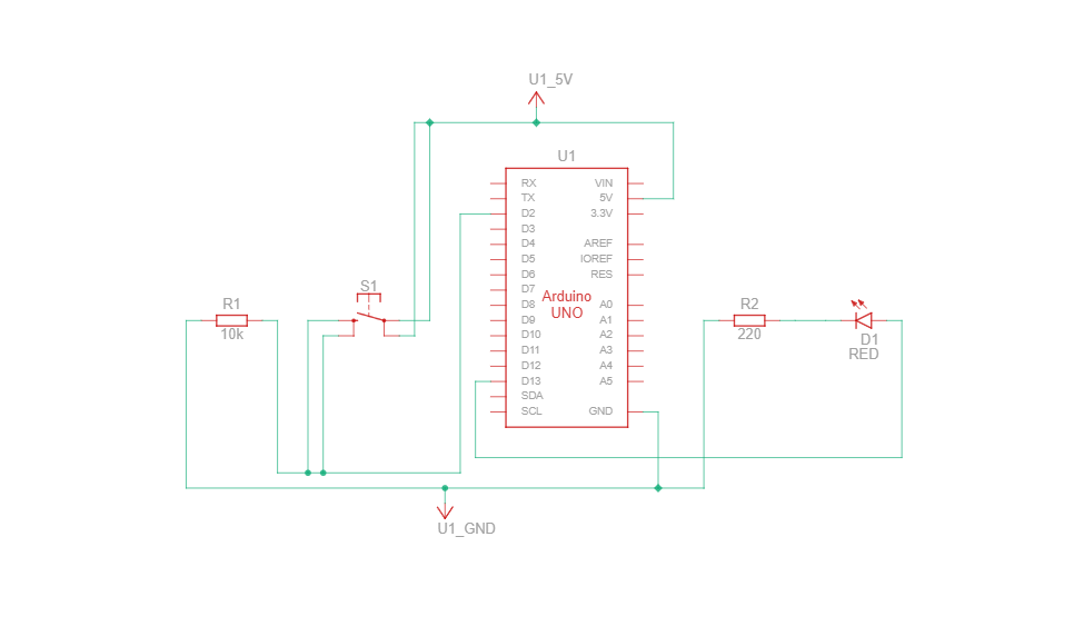
Circuit Diagram
💡Tip: 10k ohms is a sweet spot, strong enough to keep the pin LOW, but not blocking the real signal when the button is pressed.
What You'll Need
- Arduino Uno x 1
- Breadboard x 1
- LED x 1
- 220Ω Resistor (for LED) x 1
- 10KΩ Resistor (for Push Button) x 1
- Push Button x 1
- Jumper wires x 7
- Arduino Uno USB Cable A to B x 1
- Arduino IDE installed
Instructions
- Connect the top-right side of the push button to pin 2 on the Arduino.
- Connect the bottom-right side of the push button to GND through a 10kΩ resistor.
- Connect the bottom-left side of the push button to VCC.
- Connect the LED's long leg (anode) of the LED to pin 13.
- Connect the short leg (cathode) to GND with a 220Ω resistor.
- Connect jumper wires (GND & VCC) from the breadboard to GND & VCC on the Arduino.
- Plug your Arduino into your computer using the USB cable.
- Open the Arduino IDE, and paste in the code below.
- Under Tools, select your board type and COM port.
- Click Upload. Press the push button and the LED should turn on!
The Code
// Set up the pins, we're giving them easy-to-use names
const int buttonPin = 2;    // The button is wired to pin 2
const int ledPin = 13;      // The LED is wired to pin 13

void setup() {
  // Tell the Arduino what the pins are doing
  pinMode(buttonPin, INPUT);   // We're going to read the button (so it's an INPUT)
  pinMode(ledPin, OUTPUT);     // We're going to control the LED (so it's an OUTPUT)
}

void loop() {
  // Check if the button is being pressed right now
  int buttonState = digitalRead(buttonPin);  // Reads HIGH when pressed, LOW when not

  // If the button is being pressed...
  if (buttonState == HIGH) {
    digitalWrite(ledPin, HIGH);  // Turn the LED ON
  } else {
    digitalWrite(ledPin, LOW);   // Otherwise, turn the LED OFF
  }

  // This repeats forever, it's the "loop"
}
Schematic Diagram
Schematic diagrams show how current flows and how components connect logically, not just physically.
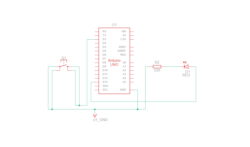
Circuit Diagram (INPUT_PULLUP Version)
In this setup, one leg of the button connects to GND, and the other to digital pin 2. No resistor is needed, the Arduino uses its internal pull-up resistor.
Code for INPUT_PULLUP
const int buttonPin = 2;      // Pin connected to pushbutton
const int ledPin = 13;        // Pin connected to LED

void setup() {
  pinMode(buttonPin, INPUT_PULLUP); // Use internal pull-up resistor
  pinMode(ledPin, OUTPUT);          // Set LED pin as output
}

void loop() {
  int buttonState = digitalRead(buttonPin); // Read the button input

  // Logic: Button pressed = LOW (since it's connected to GND)
  if (buttonState == LOW) {
    digitalWrite(ledPin, HIGH);  // Turn on LED
  } else {
    digitalWrite(ledPin, LOW);   // Turn off LED
  }
}
Schematic Diagram (INPUT_PULLUP Version)
Schematic diagrams show how current flows and how components connect logically, not just physically.
© 2025 Ohmly